6. Parallel circuits experiment
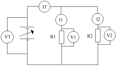
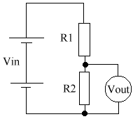
R1 R2 VT V1 V2 IT I1 I2 RT 1K 2K 5.0 v 5.0 v 5.0 v 7.5 mA 5.0 mA 2.5 mA 667 In this experiment, we were looking at the characteristics of a parallel circuit experiment. Let's look at a couple of things.
The reason the current is different is because it splits between the first & second bits. It splits if different proportions, because of the value of the resistors.
The reason the voltmeters are displaying the same reading is because they are all connected across the battery. The ammeters have no resistance, so you can forget about them. If you move the voltmeter's connections to the place where the circuit splits, it makes no difference.
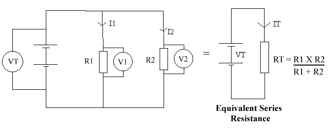
- The currents add together ( IT = I1 + I2 )
- The voltages (p.d's) are all equal ( VT = V1 = V2)
- The overall resistance is less than either of the the resistors
present.
In resistors, we change the form of energy from electrical energy to heat energy. Power is the rate at which energy is converted. The first equation is a general physics equation. The second is the one you want. It's the same thing, only expressed in electrical terms.
- Power = Energy converted / time taken
- Electric power = Current * Voltage
- P = I * V
Power is measured in Watts. Other power equations are:
- P = I x V
- P = I² x R
- P = V² / R
The power rating of a resistor is the maximum power that it can take before overheating. If the power rating is exceeded, the resistance may change & it may become an open circuit, or a short circuit.
Usually, the power rating for small resistors is ¼ or ½ watts. For larger resistors, 1W, 2W, or even 10W is available.
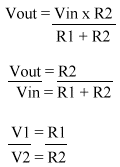
The potential divider is used to give a reduced voltage. It divides in the same ratio as the resistors. They can seem quite complex at first, but they're really not that difficult once you get the hang of them.
There are many formulas relating to the potential divider.
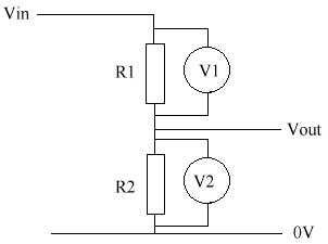
10. Measuring voltage dividers
Vin (V)
R1
R2
Calculated Vout
Measured Vout
10
4K7 1KO 1.75
1.71
10
2K2 3K3 6
5.77
10
10K 5K6 3.5
3.64
10
3K 1K 3
2.77
12
6K 1K 2
1.77
10
1K59 1K 6.3
6.34
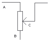
A potentiometer is a variable potential divider. Below is the circuit diagram, & a diagram of its construction. The idea is that you move a slider along a track (it's normally a coil), and depending on the poistion on the coil, the resistance will vary between each side.
Presume Vin is set at 10V.
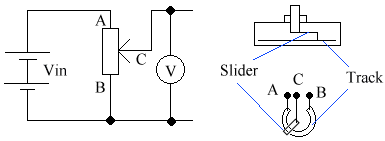
- If slider is set at A, then V = 10V.
- If slider is set at B, then V = 5V.
- If slider is set at C, then V = 0V.
Any voltage between Vin & 0V (i.e., no voltage drop) is obtainable.
A potentiometer can be used as a variable resistor, by only connecting 2 of the terminals.
12. Logic - Digital electronics
In digital electronics, there are only 2 levels: on or off. These are normally represented as a 0 for off, & a 1 for on. It is also sometimes represented by a true / false conditions. The actual values can be anything, such as 5V or 0V. We use logic in gates. We display the results in a truth table.
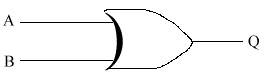
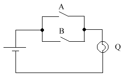
For example, a fire alarm must sound if a switch is pressed (A) OR if a smoke detector is activated (B).
A
B
Q
0
0
0
0
1
1
1
0
1
1
1
1
OR-gate Truth Table
sample chip: 7432 (quad 2-input Or-gate)
This is basically saying that Q comes on when either A or B are on. Note that my drawing skills are not very good, especially when you couple them with a mouse. So the OR gate is meant to look like an arrowhead. The general shape is there, but you just need to straighten it up a little. Note that the circuit diagrams become a little complicated now. So from now on, if there is a dot at a crossing of 2 wires, then the wires are joined. If there is no dot, then the wires just cross, with no connection or electrical conductivity between them.
This circuit can be represented using the following circuit diagram:
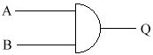
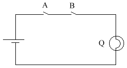
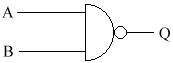
This gate turns on when both A AND B are on. For example, we want the heating to come on (Q) if the time switch is on (A) and the temperature is below 20ºc (B)
A
B
Q
0
0
0
0
1
0
1
0
0
1
1
1
AND-gate Truth Table
sample chip: 7408 (quad 2-input AND-gate)
This can be represented using the following circuit diagram:
Q will be on if both A & B are on.
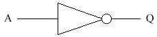
The NOT gate (Inverter)
I will put the washing out (Q) if it is NOT raining (A)
A
B
0
1
1
0
Inverter Truth Table
sample chip: 7404 (hex inverter)
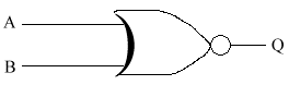
A porch light (Q) must come on if it neither daylight (A) NOR after midnight (B)
A
B
Q
0
0
1
0
1
0
1
0
0
1
1
0
NOR-gate Truth Table
sample chip: 7402 (quad 2-input NOR-gate)
Q will be on if neither A nor B are on.
I will have breakfast today provided it is bacon NAND tomatoes (As long as it isn't bacon & tomatoes together).
A
B
Q
0
0
1
0
1
1
1
0
1
1
1
0
NAND-gate Truth Table
sample chip: 7400 (quad 2-input NAND-gate)
The NAND gate is the most difficult to understand. All the others are English words, so they are easier to understand. The thing about NOR & NAND gates is that they are like OR or AND gates, followed immediately by a NOT gate. So if you find them just to difficult, you can always remember them like that.
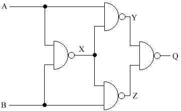
When asked to find a truth table for a circuit, it can sometimes be helpful to use extra letters. These are usually X & Y, but any letters can be used. The easiest way would be to look at the gate below.
There is one other gate that is very useful. It is called the eXclusive OR (XOR). You can buy this in a chip, or you can build your own. It can be constructed in the following way.
A
B
X
Y
Z
Q
0
0
1
1
1
0
1
1
1
1
0
1
0
0
1
0
1
1
1
1
0
1
1
0