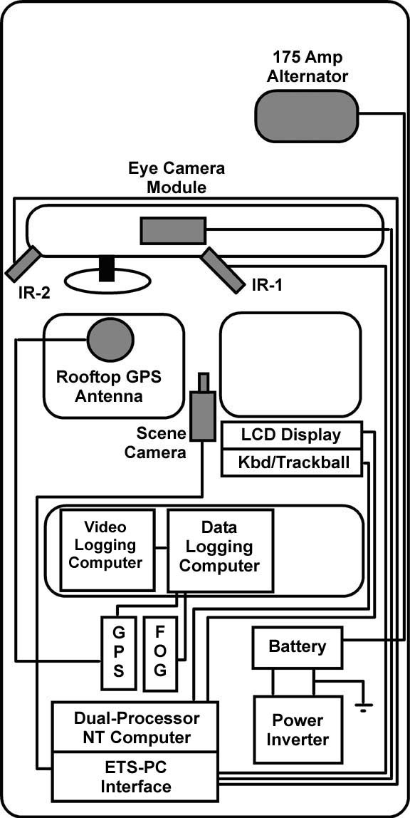
ETS-PC Vehicle Schematic
Professor Frank Schieber, Heimstra Human Factors Laboratories, University
of South Dakota
This schematic drawing depicts the main subsystems of the ASL
ETS-PC eyetracker
as currently configured in the Heimstra Labs' instrumented research vehicle
(a 1998 Toyota Avalon).
Subsystem Descriptions:
Electrical system. The "stock" alternator was capable of supplying 100 amps of current but ONLY at highway speeds. Since our research protocols often require much time spent "at idle" we needed to upgrade the alternator with one capable of supplying 100 amps at typical engine idle speeds. We purchased a Model 20-AN160JL high-output alternator from Wrangler NW Power Products, Inc. 810 N. Graham St., Portland, OR 97227 (www.wranglernw.com). Their engineers custom-built the alternator so that it could be directly "swapped" for the OEM unit without the need for any modification of the mounting brackets or electrical connections (except for upgrading the gauge of the power output cable).
A pair of 0-guage cables (+12 V and ground, respectively) run from the upgraded alternator to a deep-cycle battery located in the vehicle's trunk compartment. Current in the +12 V cable is fused via a 200 amp circuit breaker located in the engine compartment. The deep-cycle battery in the trunk is connected to a Cotek Model S1500-112B22 1500 watt pure-sine power inverter (purchased from DonRowe.com). This power inverter has performed flawlessly over several hundred hours of operation. It runs cool and has front-panel indicators displaying the DC input voltage being supplied by the alternator/battery as well as the AC output current (The deep-cycle battery was added to prevent a "catastrophe" should the driver inappropriately "cut" the engine before the data collection computers had been properly shut down, etc.).
Eye Camera Module. The ASL ETS-PC uses computer-controlled servo-mirrors and a remotely focused camera to continuously collect images of the driver's right eye. The mirrors are used to follow the eye as the driver's head moves through a predefined 3D envelope of space (see Eye Camera Module for additional details). The eye camera is setup to view infrared light that is stroboscopically presented via a pair of IR illuminators mounted to the left and right of the steering wheel. This configuration enables the ASL ETS-PC to operate over a very wide range of ambient illumination conditions (bright sunlight to dark nighttime). The instrument panel of the 1998 Toyota Avalon research vehicle had to be modified to accommodate the relatively large footprint displaced by the Eye Camera Module. This work was performed by Classic Imports, 301 W. 43rd Street, Sioux Falls, SD 57105. They moved two air conditioning/heater ducts and several electrical circuits to make the necessary room for the module. A custom bracket was fashioned to allow easy insertion and/or removal of the Eye Camera Module. The mounting bracket was affixed to a major structural support that ran the width of the instrument panel to minimize spurious vibrations. Finally, they covered the mounted Eye Camera Module with a reconstructed instrument panel equipped with a "black glass" (IR transmitting) viewing port. Five cables run from the instrument panel to the ETS-PC Interface unit in the trunk compartment. These cables provide power to the IR illuminators, collect video signals from the eye camera, drive the remote focusing motor as well as the vertical and horizontal mirrors used to track driver head movements.
Dual-Processor NT Computer. The ASL ETS-PC control software operates on a specially configured dual-processor computer running Windows NT 4.0. This unit is shock-mounted in the trunk compartment. The operator interface to the control software is mediated by a high-contrast, flat panel display mounted on the rear of the front passenger seat (making it easily viewable from the rear passenger seat). A keyboard equipped with an integrated trackball sits on the experimenter's lap during operation of the eye tracker. The trackball is used as a replacement for the mouse interface. Power for the main control computer is supplied directly from the 1500 watt AC power inverter (described above).
Video Logging Computer. The ETS-PC eye tracker generates continuous video of the forward driving scene with an overlay indicating the current gaze position. The video logging computer digitizes and compresses this video stream (as well as audio from an in-vehicle microphone) in real-time and stores the resulting MPEG4 movie on a 1.5 GB ramdisk (www.winsoft.sk/ramdisk.htm). This computer is a Windows 2000 platform built upon an Intel D865GBF motherboard with a 1.8 GHz Pentium 4 processor, 2 GB RAM, onboard graphics, 60 GB hard drive, USB ports, etc. Video digitization is performed at 30 fps using a Hauppauge WinTV-PCI board (www.hauppauge.com). Real-time video and auditory capture and compression is performed using a public domain software application known as VirtualVCR (Visual C++ source code at virtualVCR.sourceforge.net). Each video frame is "time stamped" with a unique sequential number via a custom DirectShow video filter implemented via C++. This module writes the sequence number in human and machine-readable (barcode) form into the lower left corner of each video frame prior to the video compression stage and simultaneously passes this sequence number to the data logging computer (see below) via a pair of Acces PCI-DIO-48 digital I/O boards and a modified 50-pin ribbon cable (www.accesioproducts.com). The data logging computer uses this timestamp to synchronize simultaneous data streams to the video record of the driving scenario.
Data Logging Computer. Although the dual processor NT computer used to run the ETS-PC software can log gaze position and pupil size at 60 Hz, it has no facility for synchronizing eye movements to externally collected data streams. Hence, a separate MS-DOS (real-time) computer with multiple interrupt-driven serial ports is used to collect external data and synchronize the storage of these data streams to the video log of the driving scenario (using the timestamp values passed by the video logging computer). Data from real-time GPS, fiberoptic laser gyroscope (see below), and related vehicle status parameters are then made available for off-line analysis with custom software developed using Visual Basic 6.0 (allowing synchronization to the video record on a frame-by-frame basis if necessary).
Global Positioning System. A Starlink Model DNAV-212G global positioning system with differential correction was used to continuously determine vehicle position (www.starlinkdgps.com). Differential GPS data collected with the DNAV-212G yields sub-meter accuracy and is computed in near real-time. Position calculations are made and output at a rate of 10 Hz over a high-speed RS232 serial interface to the data logging computer. The "age" of each position fix varies from approximately 15-40 msec (depending upon the number of satellites being tracked) and is output along with the latitude and longitude data allowing variations in latency to be used to "correct" the position estimate during off-line analysis. Given D-GPS data collected from critical landmarks along the driving course (e.g., highway sign stimuli) the real-time position estimates collected while driving can be used to determine driver-to-target distance when scoring the eye movement data record. The GPS antenna was mounted on the roof of the instrumented research vehicle just above the driver's head to maximize the accuracy of such measurements.
Fiber-Optic Laser Gyroscope (FOG). A KVH AutoGyro was mounted in the trunk compartment and connected to the data logging computer via a high-speed RS232 serial interface. This fiber-optic laser gyroscope continuously computes heading changes (yaw rate) in the road plane with an accuracy of 0.001 degrees per second (www.kvh.com). This data has been used as a proxy measure of steering instability in dual-task driver workload protocols. Validation studies using this measure are currently in progress.
High-resolution, High-sensitivity Scene Camera. The scene camera originally supplied with the ASL ETS-PC was a Pulnix Model 7DSP color composite video camera. This camera was quite suitable for daytime driving studies. However, it was not nearly sensitive enough (min = 2 lux) to adequately capture critical details of the nighttime driving environment. We replaced this camera with a high light sensitivity, high spatial resolution Genwac Model GW-902H video camera fitted with a Computar 4.5-10 mm vari-zoom lens. The GW-902H is a monochrome 1/2-inch CCD with horizontal resolution of 570 TV lines and a minimum illumination requirement of 0.0003 lux (GenwacCameras.com). This camera performed well AFTER it was fitted with an infrared "cut" filter needed to block the intense IR radiation output from the dual IR illuminators (Part no. IRC21-50R from Sunex, Inc.( optics-online.com ).
Dynamic Microphone. An amplified omnidirectional microphone (Polaris Industries Model MIC-600 www.polarisusa.com ) was used to record driver voice responses during the experimental protocols. Voice data was recorded on the audio channel of the VCR used to collect the "annotated" video output of the eye tracking device. The microphone was mounted at the base of the scene camera.
Trunk Compartment Cooling Fan. Many of the critical subsystems of the eye tracker were located in the trunk compartment of the instrumented research vehicle. Heat build-up in the trunk compartment on a hot summer day was quite considerable (temperatures approaching 130 degrees-F were not unusual). Needless to say, these high temperatures were incompatible with the dual high-speed Pentium processors used to run the ASL ETS-PC software. To address this problem we installed a quiet, high-speed DC fan between the passenger compartment and the trunk (as well as creating a 1 ft-square return air vent to foster adequate air circulation). This setup effectively extended the reach of the vehicle's air conditioning system to the trunk and resulted in trunk temperatures that were compatible with nominal operating conditions for our computer systems.
USD Home Page - Professor Schieber's Home Page - Previous Page