Previous page

19. The Capacitor

The capacitor stores electric charge - note that this is entirely different to current & voltage. I'll be explaining this in the dictionary of terms, currently under construction. Once charged, as in the circuit below - the capacitor will store the charge. This charge will not go anywhere (actually, it will slowly leak away - but at an insignificant rate) & can be used to power a circuit for a very short while - lighting a small torch lightbulb for 5 seconds is an impressive feat for a capacitor. They are usually used in a delay circuit - I'll explain why later. Most capacitors are polarity sensitive - ie. they won't work properly if you insert them the wrong way round.

Note that these little dudes will quite happily blow up if you put too much current or voltage through it, or if you connect it the wrong way round (although that only applies to the electrolytic capacitor). They are more than capable of drawing blood, but your limbs are safe & and it's quite difficult to blow them up without trying, as long as you take care when designing your circuits.

Capacitors have a large production spread (see the resistors section if you don't know or can't remember what that is) - it can be up to ±50% .  

CapacitorPlatesSymbol.gif (2492 bytes)

A capacitor consists of two metal plates very close together, separated my an insulator. A charge flows onto the plates & remains there when the battery is removed. The charge stored depends on on the capacitance of the capacitor, which is measured on Farads (F). 1F  is a very large capacitance. Below is a table of common capacitances - if you haven't got the symbol font installed on your computer, the first symbol will not display correctly. It should be like a u, with a long tail leading to it from the right. Like a reversed y.

Units in shorthand Value in Farads Scientific notation Written as
1mF 1/1,000,000 F 10-6 microfarads
1nF 1/1,000,000,000 F 10-9 nanofarads
1pF 1/1,000,000,000,000 F 10-12 picofarads

Types of capacitor

Non-electrolytic capacitor (e.g., ceramic disc)

NonElectrolyticCapacitorSymbol.gif (987 bytes)

  • Fairly small capacitance - normally about10pF to 1mF
  • No polarity requirements - they can be inserted either way into a circuit.
  • Can take a fairly high voltage.

Variable capacitor

VariableCapacitorSymbol.gif (1031 bytes)

  • Adjustable capacitor by turning a knob - similar to variable resistors.
  • The maximum capacitance available is about 200pF.
  • Used in radios.

Electrolytic capacitor (polarized)

ElectrolyticCapacitorSymbol.gif (1047 bytes)

  • Large capacitances - 1mF to 50000mF
  • Must be corrected the right way round - the white terminal on the diagram above signifies positive.
  • Low voltage rating - about 25V.
  • They have a significant leakage current - this means that they will lose the charge stored over time.

Tantalum capacitor (polarized)

ElectrolyticCapacitorSymbol.gif (1047 bytes)

  • These have the same properties as the Electrolytic capacitor, but they are physically smaller & have lower leakage. As a result, though, they are more expensive.   

Charging a capacitor

Normally, a capacitor will charge in about a millisecond. However, we can slow it down by putting a resistance in series with it.

ChargingACapacitor.gif (1756 bytes)

In this experiment, there is a new value introduced - the time constant. This is what you get if you multiply the resistance with the capacitance in the following circuit. The actual time, however, will not be this value, due to the production spread. For this experiment, we are seeing how long it takes for the capacitor to charge up to 5V. The switch is in the circuit to drain the capacitor. Note that below we are dealing in microfarads. Note also that s is the symbol for seconds.

Capacitance (mF) Resistance (M) Time (s) Time Constant
100 1 100 100
100 0.1 10 10
100 0.47 45.5 47
330 1 535 330
33 3.3 97 99

The capacitor charges rapidly at first, then slows down. The time to taken to charge is proportional to capacitance * resistance, also known as C*R.

Timing circuit

The bulb comes on a short time after the switch is opened, when the capacitor voltage reaches 0.7V.

20. The Astable (or pulse generator)

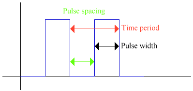
The astable is not stable in any state. This means that it continually changes between a giving a logic 1 & a logic 0. This is a diagram of a wave from an astable:

AstableTermsGraph.gif (3920 bytes)

  • Pulse width is the time that the output is high.
  • Pulse spacing is the time that the output is low.
  • The Time Period is the time for a complete cycle.
  • Frequency is the number of oscillations per second. It is 1 / Time Period. It is measued in Hertz, or Hz.
  • The mark to space ratio is the pulse width / pulse spacing.

21. The Cathode Ray Oscilloscope (CRO)


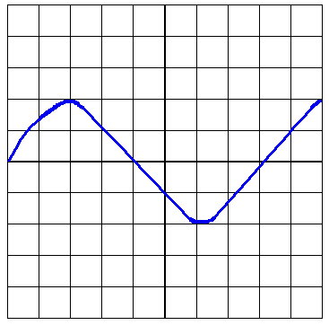
An oscilloscope is used to measure high frequencies & voltages of high frequencies. Here is a picture of a wave. This is known as the trace:

CROGraph.gif (5769 bytes)

There are many controls on an oscilloscope. Here are the most important ones:

  • Vertical calibration - this sets how many volts there are per division on the screen. In the picture above, we have a vertical calibration of 0.5V/div. The trace is 2 div. high, so it has a 1V peak voltage.
  • Time Base - this is the horizontal calibration, or where the spot would move uniformly across the screen. eg. 2ms/div. Our trace is 8 divisions/cycle. The time period = 8 div * 2ms/div = 16ms. Frequency = 1/T = 1/0.016 = 62.5 Hz.
  • Trigger - gives a stable trace. It ensures that each scan of the screen starts at the same point of the waveform.


22. The 555 timer as an astable

The 555 timer is a very versatile chip. Here you will learn how to use it as an astable.

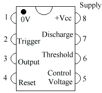
The 555 comes in a Dual In-Line (DIL) Package. This means that it has two rows of pins. Here is a picture of a 555, much enlarged. The text is the name of the pin and the number is the pin number.

555PinDiagram.gif (5061 bytes)

The more observant of you will have noticed the semicircle at the top and the little blck circle in the top right. This is to tell you where the top of the chip is. When you buy the chip, it is only about 1 cm long, so there is no room to write the pin names. So the chip maker cuts a little semicircular bit out at the top. Sometimes there is also a black dot to show where pin 1 is.

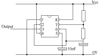
To use an astable, you need to use this circuit:

555CircuitDiagram.gif (3823 bytes)


You don't need to know how this circuit works, but it is to do with the capacitor charging until it needs to discharge through the threshold and the trigger. You can change the size of the pulses by changing the resistances and the capacitance of the capacitor on the bottom right.

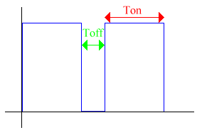
555Graph.gif (2504 bytes)

The graph above is an illustration of a 555 output. There are some formulas for a 555. R1 is the top resistor, R2 the bottom, and C the capacitor in the bottom right:

Ton = 0.7 * (R1 + R2) * C
Toff = 0.7 * R2 * C
Time period = ((R1 + 2R2) * C) / 1.44

Next page