(via a simple LED Driver Circuit)
The LED
![]()
The LED
![]()
An LED is the device shown above. Besides red, they can also be yellow, green and blue. The letters LED stand for Light Emitting Diode. The important thing to remember about diodes (including LEDs) is that current can only flow in one direction.
To make an LED work, you need a voltage supply and a resistor. If you try to use an LED without a resistor, you will probably burn out the LED. The LED has very little resistance so large amounts of current will try to flow through it unless you limit the current with a resistor. If you try to use an LED without a power supply, you may be highly disappointed.
So first of all we will make our LED light up by setting up the circuit below.
![]()
Step 1.) First you have to find the positive leg of the LED. The easiest way to do this is to look for the leg that is longer.
Step 2.) Once you know which side is positive, put the LED on your breadboard so the positive leg is in one row and the negative leg is in another row. (In the picture below the rows are vertical.)
Step 3.) Place one leg of a 220 ohm resistor (does not matter which leg) in the same row as the negative leg of the LED. Then place the other leg of the resistor in an empty row.
Step 4.) Unplug the power supply adapter from the power supply. Next, put the ground (black wire) end of the power supply adapter in the sideways row with the blue stripe beside it. Then put the positive (red wire) end of the power supply adapter in the sideways row with the red stripe beside it.
Step 5.) Use a short jumper wire (use red since it will be connected to the positive voltage) to go from the positive power row (the one with the red stripe beside it) to the positive leg of the LED (not in the same hole, but in the same row). Use another short jumper wire (use black) to go from the ground row to the resistor (the leg that is not connected to the LED). Refer to the picture below if necessary.
The breadboard should look like the picture shown below.
![]()
Now plug the power supply into the wall and then plug the other end into the power supply adapter and the LED should light up. Current is flowing from the positive leg of the LED through the LED to the negative leg. Try turning the LED around. It should not light up. No current can flow from the negative leg of the LED to the positive leg.
People often think that the resistor must come first in the path from positive to negative, to limit the amount of current flowing through the LED. But, the current is limited by the resistor no matter where the resistor is. Even when you first turn on the power, the current will be limited to a certain amount, and can be found using ohm’s law.
The omnipresent usefulness of Ohm's Law:
[ Voltage (volts) = Current (amps) X Resistance (ohms) ]
Ohm's Law can be used with resistors to find the current flowing through a circuit. The law is I = V/R (where I = current, V = voltage across resistor, and R = resistance). For the circuit above we can only use Ohm's law for the resistor so we must use the fact that when the LED is on, there is a 1.9 voltage drop across it (BTW: The voltage drop varies with the type of LED). This means that if the positive leg is connected to 5 volts, the negative leg will be at 3.1 volts (i.e, 5.0-1.9=3.1). Now that we know the voltage on both sides of the resistor and can use Ohm's law to calculate the current. The current is (5.0-1.9) / 220 = 3.6 / 2000 = 0.0014 Amperes = 14 mA
This is the current flowing through the path from 5V to GND. This means that 14 mA is flowing through both the LED and the resistor (since they are wired in series). If we want to change the current flowing through the LED (thus, changing the brightness) we can change the resistor. A smaller resistor will let more current flow and a larger resistor will let less current flow. Be careful when using smaller resistors because they will get hot. Also, some LED will be destroyed if you operate them beyond their maximum current rating...so don't use a resistor that's so small that you will generate an exceedingly high current (note: our LED has a maximum operating current of 20 mA).
Next, we want to be able to turn the LED on and off without changing the circuit. To do this we will learn to use another electronic component, the transistor.
The Transistor
Transistors are basic components in all of today's electronics. They are just simple switches that we can use to turn things on and off. Even though they are simple, they are the most important electrical component. For example, transistors are almost the only components used to build a Pentium processor. A single Pentium 4 chip has about 55 million transistors (which is why these chips get so darn hot). The ones in the Pentium are smaller than the ones we will use but they work the same way.
The transistors (2N2222) that we will use in our projects look like this:
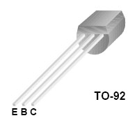
The transistor has three legs, the Collector (C), Base (B), and Emitter (E). Sometimes they are labeled on the flat side of the transistor. Transistors typically have one round side and one flat side. If the flat side is facing you, the Emitter leg is on the left, the Base leg is in the middle, and the Collector leg is on the right (note: some specialty transistors have different pin configurations than the TO-92 package described above).
Transistor Symbol
The following symbol is used in circuit drawings (schematics) to represent an NPN transistor
![]()
Basic Circuit
The Base (B) is the On/Off switch for the transistor. If a current is flowing to the Base, there will be a path from the Collector (C) to the Emitter (E) where current can flow (The Switch is On.) If there is no current flowing to the Base, then no current can flow from the Collector to the Emitter. (The Switch is Off.)
Below is the basic circuit we will use for all of our transistors.
![]()
To build this circuit we only need to add the transistor and another resistor to the circuit we built above for the LED. Unplug the power supply from the power supply adapter before making any changes on the breadboard. To put the transistor in the breadboard, separate the legs slightly and place it on the breadboard so each leg is in a different row. The collector leg should be in the same row as the leg of the resistor that is connected to ground (with the black jumper wire). Next move the jumper wire going from ground to the 220 ohm resistor to the Emitter of the transistor.
Next place one leg of the 100k ohm resistor in the row with the Base of the transistor and the other leg in an empty row and your breadboard should look like the picture below.
![]()
Now put one end of a yellow jumper wire in the positive row (beside the red line) and the other end in the row with the leg of the 100k ohm resistor (the end not connected to the Base). Reconnect the power supply and the transistor will come on and the LED will light up. Now move the one end of the yellow jumper wire from the positive row to the ground row (beside the blue line). As soon as you remove the yellow jumper wire from the positive power supply, there is no current flowing to the base. This makes the transistor turn off and current can not flow through the LED. As we will see later, there is very little current flowing through the 100k resistor. This is very important because it means we can control a large current in one part of the circuit (the current flowing through the LED) with only a small current from the input.
Back to Ohm's Law
We want to use Ohm's law to find the current in the path from the Input to the Base of the transistor and the current flowing through the LED. To do this we need to use two basic facts about the particular transistors we are using:
1.) If the transistor is on, then the Base voltage is 0.7 volts higher than the Emitter voltage.
2.) If the transistor is on, the Collector voltage is 1.6 volts higher than the Emitter voltage.
So when the 100k resistor is connected to 5VDC, the circuit will look like this:
![]()
So the current flowing through the 100k resistor is (5 - 0.7) / 100000 = 0.000043 A = 0.043 mA.
The current flowing through the 220 ohm resistor is (3.1 - 1.6) / 220 = 0.0068 A = 6.8 mA.
If we want more current flowing through the LED, we can use a smaller resistor (instead of 220) and we will get more current through the LED without changing the amount of current that comes from the Input line into the 100k ohm base resistor. This means we can control things that use a lot of power (like electric motors) with cheap, low power transistor circuits. Soon you will learn how to use a computer to control real world events. Even though the outputs of a standard Windows-based computer can not supply enough current to turn lights and motors on and off, the computer can turn transistors on and off (since this requires so little current) and the transistors can control lots of current for lights and motors. This concept is called amplification and represents the fundamental concept of computer interfacing for real world experiments.
Note:
This tutorial is heavily based upon one that originally appeared on the defunct www.iguanalabs.com web site
(A posthumous thank you to the Iguana Lab folks).