COLOUR CODES AND THEIR GENERAL USES
COLOUR CODES AND THEIR GENERAL USES

![]()
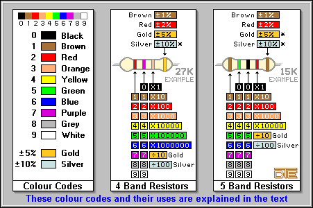
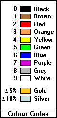 There are ten internationally recognized standard
colours used for identifying the values of a range of electronic components. Each is
assigned a numerical value between 0 (zero) and 9 (nine) in the following order; black,
brown, red, orange, yellow, green, blue, purple, grey, white.
Because these are most commonly used for identifying resistor values, this range of colours is often (incorrectly) referred to as the "resistor colour codes". In practice, these could be applied to various other electronic components, though nowadays this has largely been replaced in favour of printed abbreviations, which will be explained later.
Two other colours are also widely used; gold and silver, commonly as tolerance markings on resistors (along with certain other colours), but they also double up as division factor markings for resistances below 10 Ohms. Their assigned tolerance values are �5% for gold and �10% for silver. As division factors their values are �10 and �100 respectively.
This will sound a little confusing at the moment (to say the least!) if you are not familiar with any of these colour codes, but hopefully it should become clearer soon.
![]()
PLEASE NOTE:
The most common types of colour coded resistors are supplied with either four or five colour bands. You will also find six colour band types which includes a temperature coefficient band, but to save you further confusion, we will ignore them for the time being and concentrate mainly on the four band type, followed by a brief explanation of the five band type, since these are just an extension of the four bands.
![]()
In the very early days resistors used to resemble what looked like sub-miniature rheostats, a sort of ceramic tube, with legs like sharpened solder tags welded close to the ends of the tube. When soldered in place they stood about an eighth of an inch (3.175mm) above the circuit board. The whole body of the resistor was dipped in turquoise coloured paint, and the value was identified by a wonderful combination of dots, spots and numbers, which half the time missed the printing machine by miles! As carbon film and carbon composition resistors became more popular, coloured rings or bands around the whole body became 'the norm' for identification.
Here is a very peculiar aspect of this type of resistor manufacturing; at one time they all had only four colour bands, generally printed on a burgundy coloured body, and were physically large enough for all the colours to be seen and read easily. Nowadays, the same resistors are less than a quarter of the size, have various body colours and contain more coloured rings than Saturn! This makes identifying some of the values virtually impossible with the human eyes, even with 20:20 vision. Even experienced designers will admit to connecting some of them across a multimeter to confirm the value.
People who are quite used to reading resistor colour codes will generally be able to glance at the body and tell you within two seconds what the value of that resistor is, without the use of any conversion tables. Believe it or not, but you too will take this as second nature after some experience.
![]()
"R" = Ohms. "K" = Kilohms. "M" = Megohms.
To prevent having to write or work with a large number of figures, certain conventions are applied to how resistor values are written once they reach various quantities. Every 1,000 Ohms is know as a Kilohm (Kilo = one thousand) and is abbreviated to the capital letter "K". Every 1,000,000 Ohms is known as a Megohm (Mega = one million), abbreviated to the capital letter "M". As a couple of examples; a 4,700 Ohm resistor would be written as either 4.7K or 4K7, and 5,600,000 Ohms would be written as 5.6M or 5M6. Just for completeness, values below 10 Ohms can also be written in this way; 3.9 Ohms might also be written as 3R9, for instance.
There is no hard and fast rule governing which abbreviated method of writing them is used. Originally they were written with the decimal point in the middle, but when circuit diagrams started to appear on-mass, particularly in hobby magazines, it became apparent that due to the printing techniques and low-grade paper used, the decimal point was very often not being reproduced very faithfully. This lead to misinterpretation of the printed values and constructors building circuits that didn't work. And the problem wasn't restricted to hobby magazines either, a lot of commercial circuits and technical manuals also suffered the same omissions. Because of this, a lot of circuits started to be produced which had resistor values written using the letter in the middle method.
Another character also used to represent resistance was the Omega sign itself - ![]() , but this has now largely been replaced by the capital letter
"R". Why? Because circuit diagrams were originally drawn out on paper by
draftsmen using stencils containing the various electronic symbols and characters. With
the advent of widely available CAD machines to generate circuit diagrams, and
wordprocessors to type the written documentation, they suddenly realised that the Omega
symbol was not a standard typographical character. In the 'old days' when you purchased a typewriter* you specified what special characters (if any) were to
be included to cater for your particular line of business. But with the new digital
systems you had to make do with what was available, and the letter "R" seemed to
be the most logical one to use for resistance, so, R = Ohms.
, but this has now largely been replaced by the capital letter
"R". Why? Because circuit diagrams were originally drawn out on paper by
draftsmen using stencils containing the various electronic symbols and characters. With
the advent of widely available CAD machines to generate circuit diagrams, and
wordprocessors to type the written documentation, they suddenly realised that the Omega
symbol was not a standard typographical character. In the 'old days' when you purchased a typewriter* you specified what special characters (if any) were to
be included to cater for your particular line of business. But with the new digital
systems you had to make do with what was available, and the letter "R" seemed to
be the most logical one to use for resistance, so, R = Ohms.
![]()
COMMONLY USED ON CARBON FILM RESISTORS
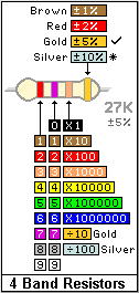 The figure on the
left shows a four colour banded resistor, together with a conversion chart to enable you
to calculate the value of any of this type. All of the colours must be converted to their
assigned values in order to calculate the resistance, and the result is always produced in
Ohms.
INVALID COLOURS:
Notice how certain colours have been omitted from the first and third columns. This is
because column one will never contain black, and column three will never have a colour
with an assigned value above 6, since basic resistor values range from 1 Ohm - brown,
black, gold, to 10 Megohms - brown, black, blue. Using our 27K example, the resistance is
calculated as follows;
THE SIGNIFICANT FIGURES and MULTIPLIER BANDS:
The first two colours represent two numeric values known as the significant figures, which
are simply written down as they appear, ie; a "2" and a "7". Next, the
multiplier band indicates how many zero's to write down after the first two digits, and
here we need three of them - "000". That's it! You now have the resistance
value, in Ohms, of that resistor - 27,000 Ohms. Since every 1,000 Ohms represents a Kilohm
or "1K", the value in the example works out to be 27K.
GOLD or SILVER MULTIPLIER BAND:
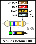 Irrespective of the value, these resistors MUST
have four colour bands. However, only values from 10 Ohms upwards can be represented with
the "usual" colour range from black to white, since the minimum valid colour
sequence is Brown, Black, Black - 10 Ohms. The figure on the right shows how values below
10 Ohms are represented. Here, gold or silver are used for the multiplier band, only now
this means the calculated resistance value must be DIVIDED by 10 or 100 respectively. In
our example a 5.6 Ohm resistor is shown, but the same applies to all values below 10 Ohms.
If the multiplier band was silver, this value would be 0.56 Ohms. However, it is very
unlikely nowadays that you will find these types of resistors with a silver multiplier
band.
THE TOLERANCE BAND:
Getting back to our 27K example, the fourth band indicates the tolerance of that
resistance as a percentage. If the tolerance band is gold, the resistance will be within
5% above or below 27K, which evaluates a tolerance of 1,350 Ohms (5% of 27,000 = 1,350).
This means the actual resistance could be as low as 25,650 Ohms, or as high as 28,350
Ohms. A gold tolerance band is possibly the most common you will find on standard carbon
film resistors. If the tolerance band is red the resistance will be within 2% of 27K, or
within 1% if brown is used. Unless you manage to get hold of some very old resistors,
silver, which represents 10% tolerance, will rarely (if ever) be seen as the tolerance
band. But it is still part of the colour code standard, so it has been included with the
rest of them.
![]()
COMMONLY USED ON METAL FILM RESISTORS
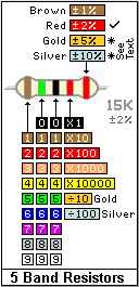 The figure on the
left shows a five colour banded resistor, together with a colour conversion chart to
enable you to calculate the value of any of this type. As with the 4 band types, all of
the colours must be converted to their assigned values to calculate the resistance, and
again the result is always produced in Ohms.
INVALID COLOURS:
Like the 4 band chart above, this one too has certain colours missing from various
columns, again where they are unlikely to be found. Column one will never contain black,
and column four will never have a colour with an assigned value above 4 - yellow. Metal
film resistor values range from 10 Ohms - brown, black, black, gold, to 1 Megohm - brown,
black, black, yellow. Calculating the value is very similar to the method explained for
the 4 band types. Using our 15K example on the left this is achieved as follows;
THE SIGNIFICANT FIGURES and MULTIPLIER BANDS:
The first three colours represent three numeric values known as the significant figures,
which are simply written down as they appear, ie; a "1", a "5" and a
"0". Next, the multiplier band indicates how many zero's to write down after the
first three digits, and here we need two of them - "00". That's it! You now have
the resistance value, in Ohms, of that resistor - 15,000 Ohms, and since every 1,000 Ohms
represents a Kilohm or "1K", the value in the example works out to be 15K.
GOLD or SILVER MULTIPLIER BAND:
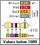 The values of these resistors MUST be represented
by five colour bands. However, only values from 100 Ohms upwards can be represented with
the "usual" colour range from black to white, since the minimum valid colour
sequence is Brown, Black, Black, Black - 100 Ohms. The figure on the right shows how
values below 100 Ohms are represented. By using gold for the multiplier band, the
calculated resistance must be DIVIDED by 10. In the example a 47 Ohm resistor is shown. If
the multiplier band was silver, the value would become 4.7 Ohms, but this is only a
hypothesis, since these types of resistors don't usually have values below 10 Ohms, so it
is very unlikely that you will ever find one with a silver multiplier band.
THE TOLERANCE BAND:
Getting back to our 15K example, the fifth band indicates the tolerance of that resistance
as a percentage. If the tolerance band is red, the resistance will be within 2% above or
below 15K, which evaluates a tolerance of 300 Ohms (2% of 15,000 = 300). This means the
actual resistance could be as low as 14,700 Ohms, or as high as 15,300 Ohms. If the
tolerance band is brown the resistance will be within 1%. Gold or Silver tolerance bands
will hardly ever be seen on these resistors. But, they are still part of the colour code
standard, so have been included with the rest of them.
![]()
USED ON METAL FILM RESISTORS
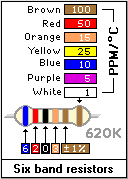 The figure on the
left shows a six colour banded resistor - 620K in our example. Before you query the
resistance, yes, this is a standard value available in this range of resistors. These are
calculated in exactly the same way as the five banded types above. The only difference is
the addition of a sixth band indicating the temperature coefficient of the resistor, which
is quoted in terms of parts per million per degrees Centigrade - PPM/�.
In the majority of cases, you will encounter these with a brown sixth band, since this
is the most common version manufactured, due to the fact it makes a reasonable stable
resistor under wide operating conditions. However, it is possible to obtain
"specials" with closer temperature coefficients than 100ppm/�C, These are used
in more precise or more temperature critical applications, so don't be surprised if you
come across them now and again.
![]()
RESISTOR STABILITY Vs TEMPERATURE
This identifies the temperature coefficient of the resistor range. Do not confuse this with the resistor value, it relates to the composition of the resistor, be it carbon film, metal film, windwound or whatever. The term "ppm/�C" is not specific to resistors, it applies to almost every single electronic component ever produced, and is a measure of how much that component's stability will drift in response to a change in temperature. This is usually measured in terms of 'parts per million per degrees centigrade' - ppm/�C. The meaning of "parts" is the units of which that component is measured, here it is Ohms. If we were referring to capacitors the units would be farads, microfarads or picofarads etc. Oscillator frequency stability would be in terms of Hertz
As a matter of interest, most resistor types have characteristics quoted up to an operating temperature of around 70�C. This must take account not only of the ambient temperature, but also any heating factors place on the component by the operation of the circuit itself. This could take the form of power dissipation, which results in quite normal self-induced heating, or secondary heating caused by the close proximity of other hotter components, such as transformers and power transistors etc.
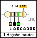 In order to make calculations easy, we will use a
carbon film resistor example of 1 Megohm - 1,000,000 Ohms (shown on the left). We will
also assume it's temperature coefficient is quoted as being �400ppm/�C, which is quite
common for carbon film resistors.
For every 1�C change in temperature, our 1 Megohm resistor could drift by up to 400
Ohms above or below it's printed value. This drift is independent of any other
specifications laid down for whatever type of resistor it relates to. In other words, no
matter what the tolerance or operating temperature range is, so long as it is operated
within the temperature range specified, the resistance could still drift by whatever
ppm/�C is specified.
In our example above, apart from it's tolerance of �5%, which allows our 1 Megohm resistor to range from 950,000 Ohms to 1,050,000 Ohms at up to 70�C (5% of 1,000,000 = 50,000 or 50K), it's temperature coefficient of �400ppm/�C also allows it to drift by up to �400 Ohms for every 1�C of temperature change. In the majority of cases, the resistance will fall as the temperature increases, so a 1�C increase in temperature could mean a drop in resistance of up to a 400 Ohms. And this applies to every 1�C increase in temperature.
Don't forget, all of these tolerance and temperature coefficient characteristics are the allowable limits for any particular range of resistor. It does not mean that they will change by the amounts given, just that they are allowed to, whilst still remaining within their specifications. You could quite easily connect two seemingly identical resistors across a multimeter and produce different results for each of them. But as long as they are both within these limits, then they are perfectly OK.
From a designers point of view, in critical applications, such as Analogue-to-Digital (A/D) conversion and temperature measurement circuits, the ppm specification is one of the most important factors dictating the type of resistors to be used, coupled with the designers anticipated operating temperature range of the finished circuit.
![]()
OR, HOW DO I KNOW IF I'M READING IT THE RIGHT WAY ROUND?
The answer to this question is simple - experience! Given all these types of resistors, with their various methods of identification, it's easy to misinterpret the value of some resistors, and it is quite common for this to happen. However, as you become more familiar with the colour codes used, you will begin to realize that only certain sequences and resistor values are available, and it shouldn't be long before you get used to what they are.
As a saving grace, you could always attempt to work out the value, then check your result against a resistor value chart to see if it's listed there. If it isn't, then try reading it again starting from the other end, then check again. This will generally only be a problem with five and six banded metal film resistors, because the standard four banded carbon film types will, almost invariably, have a gold tolerance band at one end, so you know that it must be read from the other end.
![]()
With the advances in technology, resistor sizes have shrunk enormously from their original size, and Surface Mount Device (SMD) or chip resistors are now being used in vast quantities by equipment manufacturers. These really are tiny by comparison to even todays average (say) �Watt resistors, which makes the use of colour coding impractical, not only from a manufacturing point of view, but also for the poor end user who's got to try and read them!
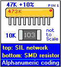 ALPHANUMERIC CODING:
To overcome this, a means of coding by numbers and letters is used instead. This method
has, in fact, been in use on various components for some years now. The figure on the left
shows a Single-In-Line (SIL) resistor network, the likes of which have been around for
years, and a modern surface mounting resistor. Please note they are not shown to scale,
some of the SMD resistors are so small they would fit between just two of the pins of the
SIL network!
HOW DOES THIS CODING WORK ?
Basically, this coding consists of three numbers, sometimes followed by a single letter.
The three numbers are actually direct representations of their equivalent colour band
values, ie; 1 represents brown, 2 represents red, 3 represents orange and so on. Where a
letter follows the numbers, this represents what would normally be the tolerance band,
which are assigned the following values; M=�20%, K=�10%, J=�5%, G=�2%, F=�1%
After studying these, you should be able to see the relationship between the alphanumeric codes and the coloured bands. For a lot of people, these are easier to read and understand than their colour coded equivalents. These are just two examples of where you will find this type of coding. There are many others in regular use too, particularly on high precision resistors and other components where the amount of available space (or lack of it) makes colour coding impractical.
![]()
![]() *TYPEWRITER: For the younger
readers, this was a sort of mechanical wordprocessor/printer made mainly of cast iron,
that was invented before electricity, and always seemed to weigh about half a tonne, even
the lightweight models! To use an old typewriter for any length of time required muscles
like Rambo, a pair of ear defenders (muffs), and the regular ability to pull the whole
machine back to with reaching distance of the keyboard, after vibrating itself into
"walkies" away from you during typing!
*TYPEWRITER: For the younger
readers, this was a sort of mechanical wordprocessor/printer made mainly of cast iron,
that was invented before electricity, and always seemed to weigh about half a tonne, even
the lightweight models! To use an old typewriter for any length of time required muscles
like Rambo, a pair of ear defenders (muffs), and the regular ability to pull the whole
machine back to with reaching distance of the keyboard, after vibrating itself into
"walkies" away from you during typing!
A single sheet of paper was inserted behind the platten and hand cranked into position ready for typing directly onto. Printing on these machines was achieved slightly different to today's printers, in that the print head remained static, and the carriage was pulled from right to left by a woven cloth belt attached to a spring loaded drum. When the paper margins were set correctly, a warning device in the form of a single 'ping' of a bell informed you that you were reaching the right hand edge of the paper, and that you only had about 10 characters left before everything came to a sudden halt! Carriage return and line feeds were invoked manually by the operator in one simple but swift operation which involved snapping sharply at the largest lever they could get hold of and gliding the carriage to the full right hand position, until either it came to an abrupt halt, the lever snapped, or the whole typewriter tipped onto it's side! The latter feature, however, was only available as standard on wide carriage models! As an optional extra on narrow carriages, this was obtained by gliding the carriage back at a much higher speed!.
These machines had no VDU screen, no memory, and no scalable fonts or graphics. However, bold type was available by simply cranking the carriage back to the words you wanted in boldface, and then typing the whole lot again over the top of what was already printed, just praying that you didn't hit a wrong key along the way! This didn't pose too much of a problem, since error correction was usually only a few inches away, in the form of a tiny bottle containing what looked like a nail varnish brush with a screw top, which was submerged in a solution which resembled white vinyl silk emulsion paint but smelled like a chemical factory! Known as correction fluid, this was simply painted over the top of the incorrect character(s) until it resembled a 3D map reference of a mini-roundabout or traffic island. This was allowed to dry for a few seconds and the correct characters were then typed on top of the painted 'hump', which not only removed any excess 'paint' and replaced it with the required character, but also had the affect of altering the appearance of that character for about the next ten or so times it was typed!
To overcome this problem, a dry transfer film version of this error correction technique was invented, know as correction paper, which made life much easier for the poor typist. All that was required here was for the film to be held over the top of the incorrect characters and then typing those characters again. The idea was to apply only the amount of correction medium required to 'hide' the incorrect characters. Unfortunately, any given area of the film could only be used once, and due to the lack of mechanical precision of the typewriter, the incorrect characters might have needed to be re-typed several times before the original print was obliterated. After such treatment, looking from the front of the typed document wasn't too bad, but unfortunately the reverse resembled something that could have been read by a blind person!
Back at the typewriter itself. Generally, these machines were monochrome devices, although a full range of grey scales was also available, based upon ribbon wear and the amount of force exerted during typing. Full colour black, red and blue versions could be had at extra cost, but only one colour was available at any one time. Wide carriage models of the typewriter were also available up to about 24 inches, which, to be frank, was an improvement on the limitations of todays modern printers! Unfortunately, the body size of the wide carriage typewriter did not match the carriage width, and bolt-on extended feet had to be fitted to counter balance the weight of the carriage when it was at the extent of it's travel.
Typing documents on these systems involved thrusting away at the 'keyboard' with all your might in order to produce an acceptable character image on the paper. This was often cursed as the cause of damage to the delicate female fingernails, which by todays average fingernail lengths were exceptionally long. The damage was caused by the fingernails catching on the key above the one they were trying to type. This perhaps was just one of the reasons why female typists who were used to using typewriters said that the close proximity of the keys on modern computer keyboards would never catch on, and would be totally unsuitable for typing, only this time the problem would not be one of damaged fingernails, but that of typographical errors caused by the fingernail typing the character above the one that the finger is supposed to be typing. Strange how nothing much has changed!