
Although Ohms Law does not apply only to resistors - as we shall see later - it seems logical to include it now, since it will provide a good reference point to the resistor details given above.
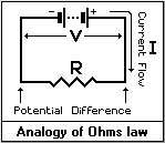 WHAT IS OHMS LAW ? :
Using the diagram on the left, Ohms Law is defined as; "Provided that the temperature
remains constant, the ratio of potential difference (p.d.) across the ends of a conductor
(R) to the current (I) flowing in that conductor will also be constant". Here endeth
the sermon !
From this, we conclude that; Current equals Voltage divided by Resistance (I=V/R),
Resistance equals Voltage divided by Current (R=V/I), and Voltage equals Current times
Resistance (V=IR).
The important factor here is the temperature. If calculations based on Ohms law are to
produce accurate results this must remain constant. In the 'real' world it hardly ever
does, and from a beginners point of view, you need not concern yourself with it any
further, since the circuits you are likely to encounter at the moment - and about 95% of
all those you will come across in the future - will work perfectly ok whether they're hot
or cold!
 OHMS LAW THE SIMPLE WAY:
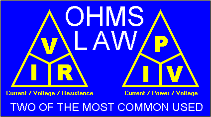
Figure 1 on the left shows the most common Ohms law triangle. Starting from any section of
the triangle, this can be read in any direction you like - clockwise, anti-clockwise, top
to bottom or bottom to top - and it will always provide you with the calculation you
require.
If you treat the (slightly diagonal) horizontal lines as divide signs and the short
vertical line as a multiply sign, and always start your calculation with whatever quantity
you're looking for, ie; "V=", "I=" or "R=" you will have all
possible formulae based on this particular Ohms law. That is; V=IxR, I=V/R, R=V/I. It
should be apparent that the formula works the other way too, that is; IxR=V, RxI=V, V/I=R
and V/R=I.
These explanations might seem a little complex, but it is simple to put into practice. Generally a helpful example would be more understandable for beginners, instead of these fancy tables, so here goes.
 EXPLANATION BY EXAMPLE:
Let's say a friend asks you to fit a red warning light into the dashboard of his/her car.
Being an electronics enthusiast you decide to use a red Light Emitting Diode (LED),
because they produce reasonably pure red light, don't give off the excessive heat of
filament lamps, they're also cheap by comparison and they look high-tech!
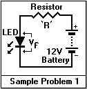
From a circuit diagram point of view, the arrangement would be as shown on the left.
CURRENT LIMITING RESISTOR:
Standard LED's cannot be powered directly from 12 Volts without fitting a current limiting
resistor in series with one of the leads, but, what value do you use ? As a general rule
of thumb, your average LED requires about 15mA of current to produce an acceptable light
output. Given this, we now have two known quantities for use in our calculation - the
voltage and the current. Using the Ohms law triangle, the required resistance is
calculated from the formula "R=V/I", which gives us 12/0.015=800 Ohms (see below
for 'Vf'). Don't forget, current is measured in Amps.
This may, at first, seem to present a problem, since 800 Ohms is not a standard value available in the E12 range. However, with this type of circuit the resistance is not critical, and the nearest preferred value will suffice perfectly well, which is 820 Ohms.
DON'T FORGET ABOUT 'Vf':
All electronic components exhibit - to a greater or lesser extent - what is know as
'dropout'. This has various abbreviations depending on the type of component to which it
refers, but they generally mean the same thing. It's actually the amount of voltage which
is used up by the component in order to function. For a standard LED this ranges between
about 1.5 - 3 volts, and for our purposes we will assume it to be 2V.
This means that, of your 12 volts from the battery, 2 volts will be used up by the LED itself, so your Ohms law calculation should be based on 10 volts instead. The true formula should actually be; (12-Vf)/0.015=666.66 Ohms (recurring for the maths wizards amongst you!). The closest value to this in E12 range is 680 Ohms, so ideally this should be the value to use. As a matter of safety, when your results end up with obscure values like this, always select the closest value higher, not the next one down.
![]()
It is possible to "manufacture" standard and non-standard resistor values to suit your own needs if the required value is not to hand. This is achieved by connecting two or more of them in parallel, series, or a combination of both. However, you need to know beforehand how they react with each other in these configurations.
 RESISTORS IN SERIES:
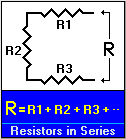
The figure on the left shows three resistors connected in series with each other. This is
the simplest way to obtain "manufactured" values. The straight line formula for
calculating the final value is; "R" = R1 + R2 + R3. In other words, irrespective
of how many resistors there are, or their individual values, the final value of
"R" will always be the sum of them all. The calculation at the foot of the image
works for any number of values connected in series, you simply keep adding them to the
list of others.
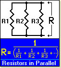 RESISTORS IN PARALLEL:
When resistors are connected in parallel with each other the calculations get a little
more tricky. The figure on the left shows three resistors connected in parallel. We will
not concern ourselves with what the three individual values are, but concentrate on what
the final value of 'R' will be by using example values. The calculation at the foot of the
image works for any number of values connected in parallel, you simply keep adding them to
the list of others inside the parenthesis. For our purposes let's say R1 is 47K, R2 is
150K and R3 is 820K. The straight line formula for the final value is; "R" = 1/(
(1/R1) + (1/R2) + (1/R3) ).
There are, what look to be a lot of unnecessary parenthesise (brackets) in this formula,
and here's the reason; with almost all electronics calculations you need to use a
calculator which gives priority to multiply and divide functions, and most scientific
calculators work in this way. Unfortunately, a lot of 'basic' calculators don't, so the
additional brackets have been shown to compensate for those which work out the figures in
the order they are entered. With a scientific calculator you can use the simplified
straight line formula; "R" = 1/(1/R1 + 1/R2 + 1/R3).
It's important to work out the values in the parenthesis before applying the final "1/" function. If you don't, then the formula becomes 1/R1+1/R2+1/R3=? If you try this on your calculator, using our example values, you will probably think you've got the wrong answer (0.02916...), but you haven't. In fact, you have exactly the right answer, it's just lacking the final "1/" function.
If your calculator has a "1/X" (one, divided by whatever is shown in the
display) function, then press that button now. If this function isn't available then place
the result in memory (making sure there was nothing in there before), clear the display
and then enter "1 ÷ MR =" or other similar sequence. The result should be
34.29K (34,290.29005 Ohms), which is correct. So, the resulting value of all three
resistors connected in parallel is 34.29K.
![]()
 Figure 2 on the left shows the second most
commonly used Ohms law triangle. This can be approached in exactly the same way as the one
above, only this time it is used for calculating power, voltage and current. The
explanations here are that; Current equals Power divided by Voltage (I=P/V), Power equals
Current times Voltage (P=VxI), and Voltage equals Power divided by Current (V=P/I).
DEMONSTRATION BY EXAMPLE:
To demonstrate the use of this triangle we will apply it to a common electrical/electronic
component - the transformer. The characteristics of these are usually quoted in terms of
their secondary winding output voltage, together with the power capabilities - in VA - of
that voltage. The term "VA" means Watts, and is derived from the formula
"Volts times Amps" (hence - VA). This is referred to as "P" in the
ohms law triangle.
 WHAT TRANSFORMER DO I
NEED ?
Let's say you have a 9 volt circuit which draws 1.5 amps of current. You want to know if a
transformer with a rating of 9V at 25VA will be adequate to power your circuit. You
already have two quantities from the transformer - the voltage (V) and the power (P or
VA), and from these you want to find out what the available current (I) will be.
Using the formula "I = P/V" from the triangle, the result is; 25 / 9 = 2.77
amps. So this transformer would be suitable for your 1.5 amp needs. As a matter of safety,
if the circuit is going to continuously draw a certain amount of current, irrespective of
what that current might be, then always use a transformer with at least 50% more available
current than your circuit requires. Never use one with "just enough" current,
because it will get far too hot, which causes characteristic changes to the voltage and
current specified. These changes are complex, and we are not going to explain them in this
beginners section, but please do exercise caution when selecting transformers.
![]()