Electronics Prototype Breadboard
|
|
An important objective of this course is for
us to learn a bit about basic electricity and electronics interfacing
between a computer and an external device. One of the ways we will
accomplish this is by "getting our hands dirty" and actually building,
testing and measuring some simple circuits. All of our hands-on work
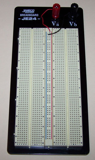
will use the Jameco JE24 (or equivalent) prototyping breadboard depicted to
the left. The JE24 breadboard enables us to easily
mount various electronic components (resistors, capacitors, LEDs, integrated
circuits, etc.) and interconnect them WITHOUT the need for soldering.
This is accomplished using various lengths of color-coded wires (see below).
This breadboard can be purchase online at Jameco.com:
Jameco Part No.
20758
Price $15.95 |
Magnified Image of the Bottom of the
Breadboard
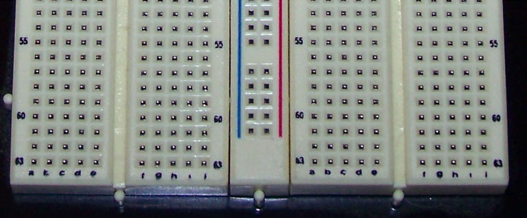
Notice that the breadboard is configured as
three basic groups of contacts:
(1) a block of 63 rows by 10 columns of contacts on the left; the rows are
labeled 1 thru 63 while the columns are labeled a through j (2)
a centrally
located power distribution bus consisting of two color coded columns of contacts
and (3) a second 63 x 10 block of contacts to the right of the power bus.
All of the contacts in a given sub-row (i.e.,
a-thru-e or f-thru-j) are electrically
connected to one another. All of the contacts in the the BLUE column of
the
power distribution bus are electrically connected to one another, as are all of
the
contacts in the RED column. Typically, one can connect the BLUE column to
the GROUND of your external power supply and the RED column to +5 VDC.
You should experiment with a pair of wires and
an Ohm-meter to "map out" the
interconnectivity of the prototype breadboard's columns and rows in order to
develop a complete mental-model of its basic configuration.
A Simple LED Prototype Circuit
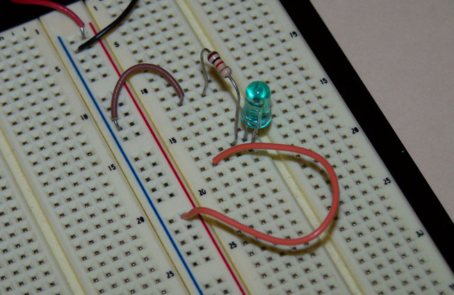
Here we see how the prototype breadboard can be
used to quickly build
and evaluate a simple circuit in which an LED is connected to power via
a current-limiting resistor (which controls its brightness). Notice that
the
green LED is mounted in column-e across rows-17 and -18. One side of
the LED is connected to a 100-ohm resistor (brown-black-red) which in
turn is connected to the ground (BLUE) power bus thru the brown wire.
The other side of the LED is connected to the + VDC side of the power
supply via the orange wire inserted into the RED (+) side of the power bus.
Professor Schieber's Home Page - Previous Page